- WIADOMOŚCI
MSPO 2017: Platform-based Thermal- and Night-Vision Systems by PCO
Not only is the PGZ Group’s PCO S.A. company a supplier of individual thermal- and night-vision systems, as it also offers comprehensive observation and warning suites that may be integrated across a variety of military vehicular platforms.
PCO company’s offer includes a wide range of products dedicated for the military vehicles and weapons systems, ranging from observation suites, through fire control suites, with self-protection suites to finish with. One of the peculiar features of the presented solutions is seen in a wide application of Polish components, including thermal vision cameras operated in MWIR and LWIR IR bandwidths.
SOD 360 Degrees Observation System
SOD system has been installed, for the first time, onboard the M120K Rak self-propelled mortar platform,. however it is also to be utilized in case of the upgraded PT-91M2 main battle tanks. The aforesaid solution was developed in a record-breaking term of 6 months, starting from the moment when proper requirements were defined by the Polish Armed Forces. This was possible thanks to the experience and competencies that had been previously acquired by the PCO company.
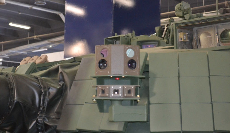
SOD is not a rotatable optronic sensor, as it comes in a form of four separate optical sensor nodes, that remain in fixed position. Even though they are fixed, proper arrangement of the aforesaid sensors on the vehicles provides a 360-degrees field of view, also allowing the vehicle crew to scroll through the panoramic view in a continuous manner, without any delays caused by the movement of the optronic sensor - both at night, as well as during the day, and in a variety of weather (fog), environmental (smoke) and climatic conditions.
SOD system is modular in its nature, and consists of the following elements:
- Four MTT modules (Thermal-Vision and Television Modules), fitted with two separate imagery tracts: thermal vision and a TV camera;
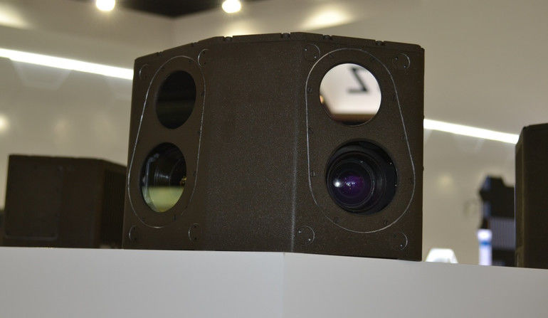
A Single SOD-system TV/Thermal Vision module. Image Credit: M. Dura
-
MOO Monitor (Observation-Operator Monitor). SOD features a touchscreen, allowing for unrestricted control of the system and also facilitating the selection of modes of operation without use of a keyboard.
-
Computer that fuses the digital video signals of the individual MTT modules into a single panoramic view, also allowing for image processing (the imagery is then displayed on the MOO monitor). There is also an option of recording the imagery on the external data storage devices.
All of the aforesaid elements are interconnected through a proper wiring, featuring a single switch that activates the whole suite. SOD system may be operated in four modes, selected by the operator via the MOO monitor:
-
“Panoramic” – the basic mode showing the full image of the situation around the vehicle in a form of a panorama strip, with a special frame marked on it, moved by the operator. The frame indicates the sector of the image that is magnified and displayed under the “panorama strip”;
-
“Modular” – the monitor screen is divided into four sections, displaying the imagery provided by each of the MTT modules separately;
-
“Directional” – the screen displays the image in line with the direction towards which the vehicle turret is turned;
-
“View” - the operator sees the image coming from two neighbouring cameras that may be fitted in one, or two neighbouring modules;
GOD-1 “Iris” Optronic System
GOD-1 “Iris” sensor suite is a multi-purpose stabilized observation suite, the design of which allows the spherical optical module to move azimuthally (360 degrees of freedom of movement) as well as within the elevation plane (-20° - +60°). The above allows the user to detect ground as well as airborne targets. Thanks to the applied interfaces and connectors, “Iris” may be integrated across a variety of platforms and weapons systems.
The system features two independent optical channels:
-
Thermal-vision one, with a LWIR camera (8÷12 µm wavelength);
-
Television one, featuring a sensor for the level of light.
Inside the whole package, a mono-pulse laser rangefinder has been placed (wavelength of 1,54 µm, eye-safe), with a range of 100 - 10.000 metres, and measurement accuracy defined as ± 5 m.
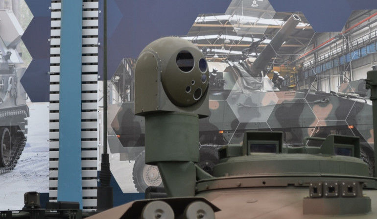
The lens applied for the TV channel may be operated with two angles of view: 3.3°x 2.5° and 10.7°x 8°, respectively, for the narrow (tele) and wide fields of view. The ranges have been defined in line with the STANAG 4351 and STANAG 4348 norms. For a 2.3×2.3 m target they are defined as follows:
-
For the narrow (tele) field of view up to: 12500 metres for detection, 4800 metres for recognition and 2500 metres for identification;
-
For the wide field of view: 5500 metres for detection, more than 1800 metres for recognition and more than 900 metres for identification.
The camera is fitted with a cooled MCT III-gen detector, with a resolution of 640x512 pixels (pixel size: 15x15 µm). NETD factor (thermal sensitivity of the camera - noise to signal ratio) is not greater than 30 mK, meaning that there is an ability to observe objects in case of which the temperature difference is as small as 0.03 K. Utilizing a cooling system physically increasing the temperature differences between the sensors and the object, and reducing the noise, made it possible to extend the range, for 2.3x2.3 m targets, up to:
-
For the narrow (tele) field of view up to: 13500 metres for detection, 5700 metres for recognition and 2800 metres for identification;
-
For the wide field of view: 5500 metres for detection, 1800 metres for recognition and 900 metres for identification.
The lens applied for the thermal-vision channel may be operated with two angles of view: 3,1°x 2,5° and 10°x 8°.
GOC-1 “Nike Stabilized Observation and Tracking Optronic Sensor
GOC-1 “Nike” sensor, similarly to the GOD-1 “Iris” system, acts as a multipurpose twin-axis stabilized system, the design of which allows the optical module to scan the 360 degrees field of view azimuthally and within -20° - +60° elevation range. The system’s purpose is to be operated in detection, observation, tracking and targeting applications, against ground-based and airborne targets.
Contrary to “Iris”, “Nike” system is a MWIR sensor. However, similarly as in case of the former solution, two independent optical channels have been applied:
-
MWIR (3÷5 µm) thermal vision;
- Television one, featuring a sensor for measuring the level of light.
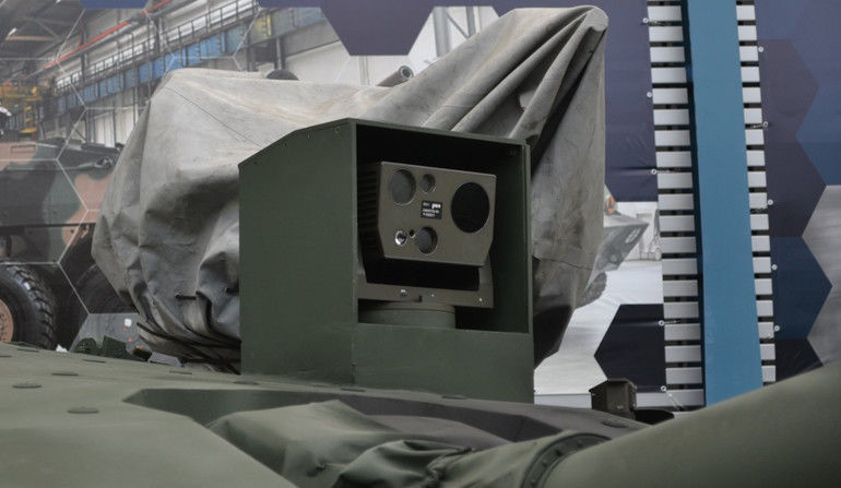
Observation and tracking GOC-1 “Nike” optronic sensor. Image Credit: M. Dura
Inside the whole package, a mono-pulse laser rangefinder is placed (wavelength of 1,54 µm, eye-safe), identical to the one used in case of the GOD-1 “Iris” system. TV cameras are also identical, with identical twin-field of view lens and ranges.
The camera is fitted with a cooled MCT III-gen detector, with a resolution of 640x512 pixels (pixel size: 15x15 µm). NETD coefficient does not exceed the value of 30 mK. The range, for 2.3x2.3 m targets is defined as follows:
-
For the narrow (tele) field of view up to: 11 500 metres for detection, 4800 metres for recognition and 2400 metres for identification;
-
For the wide field of view: 4950 metres for detection, 1600 metres for recognition and 800 metres for identification;
The lens applied for the thermal-vision channel may be operated with two angles of view: 3,1°x 2,5° and 10°x 8°.
GOC-1 “Nike” system has received the Defender award during the MSPO 2015 exhibition.
KLW-1R “Asteria” Thermal Imaging Camera
The KLW-1 “Asteria” LWIR Thermal Imaging Camera is designed to be used in fire-control and surveillance/reconnaissance systems. The aforesaid sensor has been designed for the Drawa-T fire control system used in case of main battle tanks and IFVs, but has also been installed (KLW-1R variant) on the “Rosomak” APC fitted with the Hitfist-30 turret. It is also being proposed as a solution for the newly introduced “Rosomak” APCs, that are to receive the ZSSW-30 remote-control turret modules.
“Asteria” is an IR-observation suite placed in a specially designed housing that provides the package with a higher degree of optical stability when the field of view or temperature changes, also meeting the military-grade weather-proofing and mechanical requirements. In case of the KLW-1 “Asteria” suite, the above means that the system may be operated across a temperature range from -30°C to 55°C.
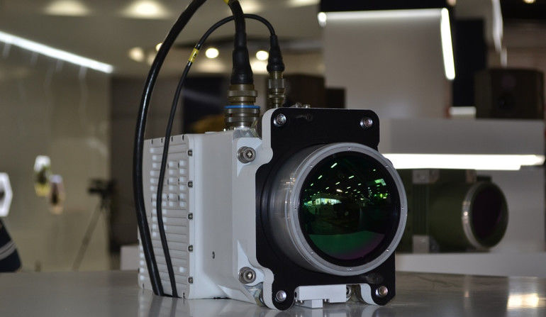
Thermal vision camera operated within the wavelength range between 7,7÷9,3 µm (LWIR bandwidth) is the main component of the suite. The camera is fitted with a cooled III-gen MCT detector, with a resolution of 640×512 pixels. NETD coefficient does not exceed the value of 30 mK. The range depends on the field of view and is shaped as follows:
-
For the narrow (tele) field of view up to: 12 000 metres for detection, more than 5000 metres for recognition and more than 2500 metres for identification;
-
For the wide field of view, up to: more than 4600 metres for detection, more than 1500 metres for recognition and more than 750 metres for identification.
The lens, developed by PCO S.A. and proposed to be used with the KLW-1 “Asteria” system, allows the user to utilize two fields of view: 3°x 2,25° and 10°x 8°, respectively for the narrow and wide fields of view. It has auto- and manual focusing ability, and has been fitted with aspherical lens element made out of germanium. Thanks to the above, the lens allows the camera to record non-distorted thermal vision imagery, also allowing the user to increase the image contrast and clarity, in order to inspect the relevant details.
The device weighs 9 kilograms and has the following dimensions: 179 x 149 x 362 mm. Additionally, the device is capable of changing polarization and orientation of the image, regulating the contrast and brightness, extracting the details, introducing the aim-points onto the image and of selecting the field of analysis for the systems of automation of the image.
KMW-3 “Temida” MWIR Thermal Imaging Camera
KMW-3 “Temida” MWIR Thermal Imaging Camera is destined to be used within the fire control suites of the anti-aircraft systems. Similarly as in case of the KLW-1 “Asteria”, KMW-3 “Temida” may be viewed as an IR-observation system placed in a specially designed housing, meeting the optical, mechanical, temperature and weather-resistance requirements applicable in case of the military-grade products.
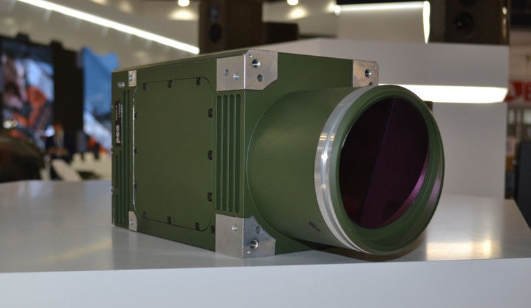
The MWIR camera is the main component of the suite, operated within the medium wavelength range of 3,7÷4,8 µm. The camera is fitted with a cooled MCT III-gen detector, with a resolution of 640×512 pixels (pixel size: 15×15 µm). NETD coefficient does not exceed the value of 30 mK.
Additionally, the device is capable of changing polarization and orientation of the image, regulating the contrast and brightness, extracting the details, introducing the aim-points onto the image and of selecting the field of analysis for the systems of automation of the image. Furthermore, KMW-3 “Temida” system also features a digital-zoom function (x2, x4).
PCT-72 Periscope-borne Thermal Vision Sight.
PCT-72 Periscope-borne Thermal Vision Sight has been designed for all of the T-72 family main battle tanks, as a replacement of the TPN-1-23-11 night sight that has been used up until recently. PCT-72 consists of the KLW-1 camera, a periscope head with a pantograph adapter, MD-1 gunner monitor with a support and headrest, MFM-2 multi-function monitor for the commander and mounting rings.
The kit may optionally include armoured cover of the periscope head, compliant with the level 2 requirements of the STANAG norms.
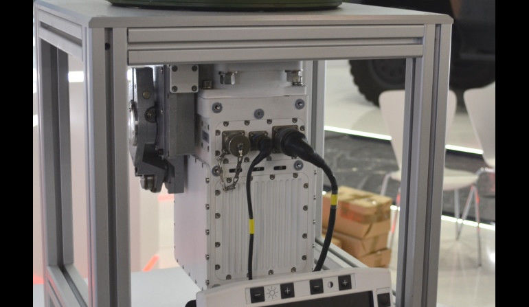
OBRA-3 Laser Warning Receiver System
OBRA-3 universal vehicle self-protection laser warning receiver allowing for detection of laser radiation directed towards vehicles or military facilities by rangefinders (operated within the wavelength from 0.6 μm to 11 μm) or laser target designators, and for notifying the crew about the threat (optically and acoustically) simultaneously indicating the radiation source heading, type and time that elapsed since the radiation was emitted.
The system may also be coupled with the smoke-grenades launcher, firing the grenades towards the direction where the source of radiation has been detected, continuously updating the coordinates as the vehicle and its turret moves and eliminating the reflected signals sent by the vehicle’s own laser rangefinder.
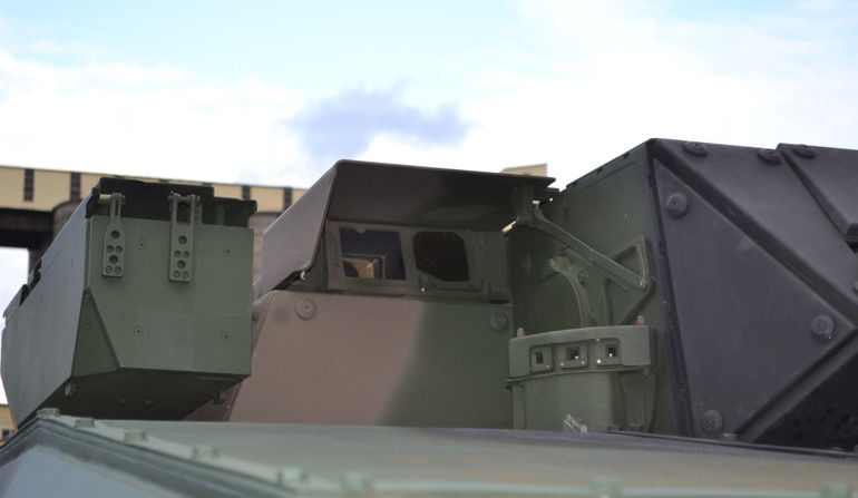
The launching of the smoke grenades may be executed manually, semi-automatically or automatically. Should one use the latest Polish GM-81 81 mm grenades (weight of 1.6 kilograms), one may create smoke-screens in two stages, as at the first stage (0.4 sec.) smoke-screen covering the vehicle itself is created, while at the second stage (after 3-4.6 secs), within several meters of the vehicle (30-40 meters) a large smoke-screen with a duration of 40-50 seconds is created. OBRA-3 may additionally work together with other vehicular systems, including the fire-control suite.
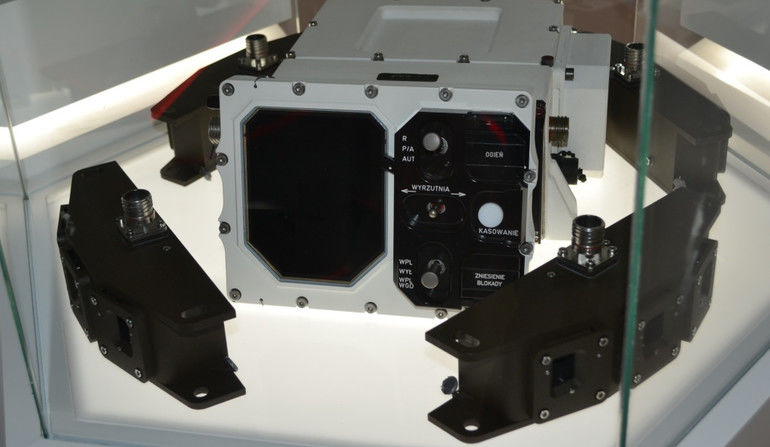
OBRA-3 system includes 4-8 fixed detection sensor packages (each weighing 1.2 kilograms), one or two operator panels (weight of 2.1 kilograms), along with a block of electronics (weight of 5.6 kilograms). The number of detection sensors depends on the platform on which the suite is installed. It is required that the field of view is covered within 360 degrees azimuthally and -6 to +30 degrees in elevation. Whereas wide field of view for each of the sensors is provided by three laser warning receivers installed in one sensor.


